
The simulation-based testing procedure of autonomous systems generally includes the generation, simulation, and analysis phases. This blog post will give an overview of these phases, how they are connected, and an example of how to use them to perform testing of an autonomous system.
This post does not pretend to be exhaustive, and the goal is to give a brief overview, so the reader can get a general idea of the phases and testing concepts.
Introduction
The last blog post introduced the characteristics and criteria to select the right simulator for the system to test. This blog post will explain the main testing procedure phases and will show how the simulation phase is framed inside a testing framework and testing procedure. Naturally, it is possible to test a system at various levels, but this blog post refers to system-level testing, and not unit testing or integration testing, which are out of the scope.
The simulation-based testing procedure of autonomous systems generally includes the generation, simulation, and analysis phases, as in Figure 1. This blog post will give an overview of these phases, how they are connected, and an example of how to use them to perform testing of an autonomous system.
This post does not pretend to be exhaustive, and the goal is to give a brief overview, so the reader can get a general idea of the phases and testing concepts.
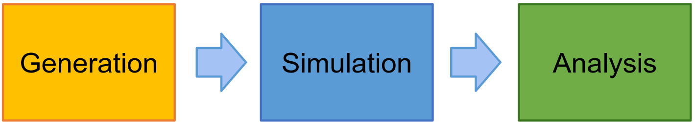
Fig. 1. The three general phases of the simulation-based testing of an autonomous system.
The three phases
There are multiple phases to test autonomous system software, and a typical testing procedure presents these phases: generation, simulation, and analysis. To make sure that the System-Under-Test (SUT) is trustable for its expected application and that it does not have faults that can lead to safety hazards and failures, the SUT will be tested with different conditions, scenarios, and parameters values. In other words, the SUT will be tested against multiple test cases with different parameters values and its behaviour will be compared to the expected behaviour that the system should show during these test cases. The test cases to run in the simulation are created in the generation phase. They can be manually designed or hard-coded, or there can be an algorithm and tools generating them. These test cases are composed of a world and a mission and will be run one or multiple times in the simulation phase. The test cases are loaded by the simulator during the simulation phase, and the logs of the events of the System-Under-Test (SUT) and the ground truth (the true values of the testing scenario, and not what is observed by the SUT) are recorded. These logs are analysed in the analysis phase, and a mechanism, called the test oracle, determines if a test has passed or failed, giving a pass or fail verdict. There can be additional steps or tools that try to understand which test case parameters are responsible for the failure. At the end of the analysis phase, a report about the analysis and the experiment is created. When a failure is detected, the report and the details of the analysis are inspected by the developers to investigate the failure and correct the fault that has generated it.
Generation
The first step in creating a test case is the modelling, during which, a representation of the environment and the mission, and the expected behaviour are created. The model is like an abstract blueprint, which contains the types of elements and parameters, their range, and the relationships and constraints between them.
This creates a search space of possible test cases. Depending on the complexity of the system and the number of parameters, this search space can be enormous. It could be unfeasible or impractical to execute every test case in simulation. It could also be inefficient, as test cases with similar parameters value could lead the system to behave similarly, making these executions redundant.
For this reason, there is a selection, in which an algorithm generates or selects which test cases to run from the space of test cases. Practically, starting from the realm of possible values in the abstract model, an algorithm will select the specific and concrete values for the parameters, creating an instantiated test case that will be used during the simulation. Depending on the test objective and SUT, there are various strategies that can be deployed for the generation and selection, like random testing, greedy combinatorial testing, search-based approaches, etc.
The generation and selection algorithm can be coded by the user, or it can be implemented using existing tools. In the case of generating test cases with constraints, LAAS-CNRS created a tool, called Testing automation Framework (TAF) [1, 2], that uses random sampling and constraints satisfaction to create test cases with structured data that respect the constraints. This tool is versatile and is customized by the user. TAF uses as input the XML model of the test case and gives as outputs files that can be read by the simulation, scripts, and various files based on the customization of the user. In Figure 2 there is an example of a testing framework with TAF integrated into the generation phase, which is coloured in light yellow.
From theory to practice
To give a practical example of a generation phase, following the yellow part of Figure 2, suppose a theoretical but realistic industrial example of an agricultural robot for weeding. In this case, the developers would first create a model of the type of world (the crops field) and the mission (weeding the crops), then use an algorithm or tool to generate the test cases with concrete values of the parameters, like the number of rows and the type of the vegetables. The generation algorithm or tool could be TAF, but genetic algorithms, hard-coded tests, or a mix of different techniques, could be also used. The test cases should contain a map of the field that the robot has to weed and instructions on how to weed the field. The expected behaviour of the robot, during the weeding, should also be defined or generated.
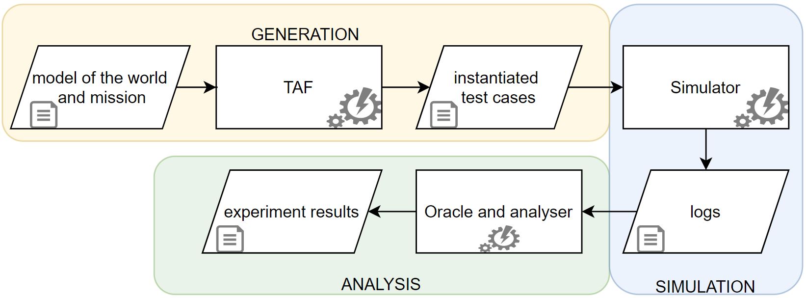
Fig. 2. A testing procedure with the phases and the TAF tool used to generate instantiated test cases.
Simulation
Once the generation phase is over, and it has created the necessary files, the simulation phase starts. This phase is coloured in blue in Figure 2. The core tool of this phase is the simulator, with criteria used for its selection described in the previous blog post. The simulator can be coupled with other tools and software for the simulation phase. The SUT will run in parallel with the simulator and will be connected to it. The simulator will use the input files (for example the files generated by TAF) to load the environment and mission of the SUT and will execute the test case described in the instantiated test case file. During the simulation, the perception of the SUT and the perception of the simulator (called the ground truth) are recorded in two logs. The logs contain events, and values of parameters, like the (x, y, z) position, angular velocity, etc. associated with the timestamps of the moment of recording. The ground truth is used in the next phase, the analysis phase, to compare it with the perception of the system and understand what went wrong during a failure, for example, to show that a collision happened because there was an obstacle in the environment, but the robot did not perceive it.
From theory to practice
Following the industrial example introduced above, the simulation phase would follow the blue part of Figure 2. In it, the test cases generated by TAF could be loaded one after the other by a simulator (like Unreal Engine or Unity), which would play the scenario contained in the test case, where the real software of the robot would navigate the crop field and follow the rows of crops, while weeding them. The perception of the robot and the simulator would be recorded in log files (text files), where each line would have the form of: “time in Unix timestamp, x_position, y_position, z_position, angular velocity w_x, w_y, w_z, additional_robot_parameters, message_sent_by_the_robot, etc.” Additional files could store more information in case of error messages sent by the robot, or pictures of what a sensor is perceiving (for example a picture of a camera of the robot, with objects that the robot cannot identify).
Analysis
When the simulation is over, during the analysis (coloured in green in Figure 2), a post-processing oracle will check the logs, the expected behaviour, and if there was a violation of the oracle properties. If there was a violation of a property, the oracle will assign a “fail” verdict. The oracle will compare the behaviour of the SUT, recorded in the simulation, against the ground truth of the simulator, and assess if the behaviour was congruent with the expected behaviour of the SUT for that test case. For example, if a system must complete a task in 10 seconds, but it took more time, the oracle will assign a “fail” verdict to the test case.
It is possible to have an additional tool or algorithm that analyses the failures to extract more information, or that tries to find the parameter values that led to the failures. This can be useful for the developers to understand what went wrong, or for the algorithm to create new test cases, if the testing framework is a testing loop. A testing loop is a closed procedure, which uses the information from the last iteration to create new test cases and restart the testing procedure. This is usually the case with search-based algorithms, that can be used to generate a new population of test cases for the next iteration. The search-based algorithms can be tweaked to investigate the search space and exploit and explore it. Of course, some algorithms are not suitable to create a testing loop, thus leaving an open testing procedure, that runs all the test cases in one iteration and that ends after the analysis phase.
At the end of the testing procedure, a report will be generated. The report includes the information extracted from the execution of the test cases and will be used by the developers to fix the bugs present in the SUT.
From theory to practice
Focusing again on the theoretical industrial example, the oracle will compare the logs, checking if the (x,y,z) position perceived by the robot is the same as the robot position that the simulator is seeing. If at a certain time, the positions differ by more than a safety threshold, like 10cm, the oracle will assign a fail verdict to this test case, create a report, and notify the developers. The developers will then check the test case, report, and logs to assess why the failure happens and identify the bug causing it, in order to fix it. This information can be sent to the generation algorithm, which can use the knowledge to create new test cases which can show more failures and expose more bugs.
Conclusion
This blog post has shown the three phases of simulation-based testing: generation, simulation, and analysis. In the generation phase, the test cases are modelled and created. Then in the simulation phase, the test cases are executed in a virtual environment and the perception of the system and simulator are logged. Finally in the analysis phase, the actual behaviour of the system is compared against the expected behavior and a pass or fail verdict is assigned to the test case, with fail indicating a behavior deviating from the expected one. The blog post has described how each phase is important for assuring a proper testing of the System-Under-Test and some examples have been given to better understand what these phases mean in practice. This blog post also reconnects to a previous post and shows how a simulator fits in a testing framework.
References
[1] Clément Robert, Jérémie Guiochet, Hélène Waeselynck, and Luca Vittorio Sartori. 2021. TAF: a tool for diverse and constrained test case generation. https://hal.laas.fr/hal-03435959
[2] Testing Automation Framework 2019. Testing Automation Framework. https://www.laas.fr/projects/taf/
About the Author: Luca Vittorio Sartori
 Luca Vittorio Sartori is an Early Stage Researcher at LAAS-CNRS in Toulouse for the MSCA ETN-SAS Project. He is interested in how to generate virtual worlds to maximize the coverage of critical test cases in simulation and how to improve the software testing of autonomous mobile robots. He has a background in automation engineering from Politecnico di Milano and research experience on metrology acquired at the WZL institute of RWTH Aachen University.
![]()