
It is not a secret that wireless technologies have already conquered our daily life but what about other aspects of our life and what about the industry? There are multiple examples of new wireless technologies coming in different industrial fields like drones assistance in line stringing or even telesurgery. The agricultural industry also adopts new technologies. In this series of blogs, we shall cover how wireless technology can help this field with timely diagnostics and which technologies could make this a reality. In the end, we shall provide some test results of the discussed technologies.
Any modern agricultural vehicle is a hybrid of machinery and industrial electronics helping to operate these leviathans. They have a number of moving and rotating parts that have to be monitored. For example, if one of the bearings on a harvester is damaged it can lead to a disbalance that will eventually result in premature wear off. If this has not been found in a timely matter then the subsequent maintenance of the harvester can cost a fortune. For this purpose, thorough diagnostics are being developed in the agricultural field. The way of monitoring is by installing detectors and sensors that are to be connected with cables and trigger the alarm if something goes wrong. The cable connection may be the easiest in terms of the factory installation but very difficult and capricious in maintenance. Moreover, these cables wear off themselves and, in some cases, they are installed in hardly accessible “entrails” of a machine. That is where wireless technology comes in! Imagine that all these bulky, lengthy cables can be replaced by wireless modules that will carry the diagnostics data. That would be indeed very helpful for nearly the whole sector! There are a number of technologies that could deal with this task. Our research team at KU Leuven investigated a number of them. This blog series will represent two different industrial technologies that are already in use in other fields, namely IOLW and SmartMesh IP. This blog episode will shed the light on the IOLW technology.
IOLW (the initialism is used for simplicity while the original name in literature is IO-Link Wireless) is the wireless extension to the well-known and established IO-Link technology. Both of them are made for factory automation. IOLW specialises in providing high reliability and low latency wireless communication and aims for the industrial market, like Industry 4.0 where the vast majority of cables will be substituted by wireless sensors. Indeed, cables especially in mechanisms that move quite often, can easily become a nuisance due to friction degradation. In addition, this issue implies higher cable requirements that increase the project’s cost and reduces the potential investors’ demand. IOLW can be applied to solve that as well as several other issues. Let us look at its topology and main principles.
Like in many communication systems, the IOLW system has topology (see Fig.1, a tribute to IO-link system extensions) with the Master and several Devices (analogy to Slaves in other systems). This is a Star communication scenario meaning that all the Devices in the network are directly connected to the Master. The Master has five tracks (so-called transceivers) each of which supports up to eight Devices resulting in 40 maximum simultaneous connections. If needed, it is possible to extend the system by creating a cell of three Masters. Thus, one can have up to 120 Devices.
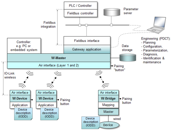
Figure1 IOLW system topology
IOLW operates in the licence-free 2.4 GHz industrial, scientific and medical (ISM) band. This band is very congested with other technologies like Wi-Fi or Bluetooth (BT). For this purpose, IOLW supports both frequency and time division multiple access (FDMA/TDMA). This helps against burst disturbances and improves wireless co-existence. Like BT, IOLW implements a frequency hopping technique with the “Blacklisting” option which improves the reliability even more.
The communication phase of IOLW is split between time slots due to TDMA. The communication itself is half duplex meaning that the Master and a Device can exchange information one way (either during an uplink or downlink phase) per time slot.
IOLW exploits cycles that are called W-cycles. Each of these cycles utilises FDMA/TDMA with a retransmission option for better reliability. A W-cycle by default (can be changed) is set up to 5 ms and consists of three duration equally sub-cycles or W-sub-cycles. How FDMA/TDMA simultaneous work is shown in Fig. 2 (a tribute to IO-link system extensions). Coloured bars on the figure during each W-sub-cycle represent W-frames (see Fig. 3, a tribute to IO-link system extensions) in which transitions or state switches between transmission/reception during downlink/uplink phases can be seen.

Figure 2 FDMA/TDMA simultaneous work during the W-cycle

Figure 3 Typical W-frame
W-frames contain information that is sent regularly like process data or cyclic communication (see Fig. 4, a tribute to IO-Link Wireless: The new Standard for Factory Automation) or during requests (acyclic communication), or events (in case of an emergent state of a sensor, for example). Process data are always sent during the first W-sub-cycle. If no retransmissions are needed, then during the remaining two W-sub-cycles on-request data can be sent. As for events, they can be sent at any time during the assigned uplink of a Device. A retransmission is needed when no acknowledgement has been received. A more detailed communication process with cyclic and acyclic communication along with retransmission is shown in Fig. 5 (a tribute to IO-Link Wireless: The new Standard for Factory Automation).
Figure 4 Data transfer mechanisms
Figure 5 Cyclic and acyclic data transfer interleaved in one W-Cycle with data transfer errors. (a) Worst-case scenario: double error occurring in cyclic data exchange. (b) An error occurring in acyclic data exchange
Since IOLW has been made for reliable communication, it sets a low packet error rate (PER). PER is used for calculating the link quality or residual failure probability (RFP). RFP depends on the maximum number of retransmissions and PER: RFP = PER1+MaxRetry. A link quality of 100 % corresponds to the RFP = 10-9. With such a low number, there cannot be high data throughputs. That is the reason why within one default W-frame of 5 ms IOLW supports payloads of 37 and 15 bytes for downlink and uplink, respectively.
IOLW, based on its progenitor IO-link technology, has already proved itself and has been developing since 2013. IOLW is an easy to integrate solution for factory automation. The agricultural sector has not adopted that technology yet. Will it be possible? We shall try to shed light on it in Part III after demonstrating the counterpart technology SmartMesh IP in Part II.
About the Author: Aleksandr Ovechkin
 Aleksandr graduated from NRU “MPEI” (Russia) with a Master’s degree which was dedicated to investigating the work of battery chargers during short circuits on the DC distribution systems. Later he joined the structural design engineering team and worked there in the electrical engineering department. While working in a company, Aleksandr didn’t quit research activity and he decided, after getting useful work experience, to completely focus on his research as a PhD student.
![]()