
Will the wireless communication of future autonomous vehicles be robust against electromagnetic disturbances? What about the continuous wave disturbance?

It is not unreasonable to assume that soon autonomous vehicles (AV) will take over one of the biggest industrial markets – automotive. Main “automotive giants” have already invested big sums of money into AV. This is only the beginning as who will make the biggest progress in this endeavor will obtain more expertise and patents and conquer the vacant market.
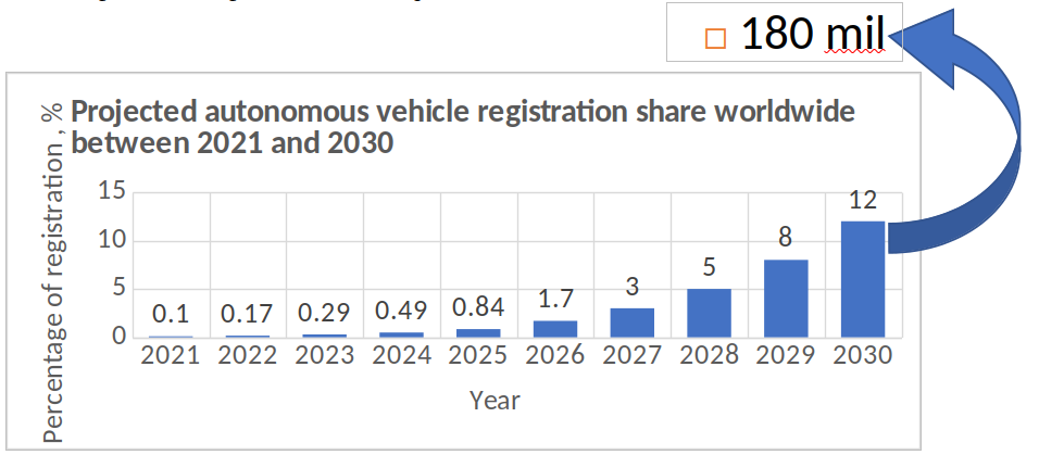
Fig. 1: AVs’ registration share between 2021 and 2030
The process to fully AVs takes time and is split into levels. There are 5 levels of automation. Test AVs are already around the world but they’re only a few of them at this moment. However, analysts from Statista assume that by 2030 there might be already 180 mils AVs (Fig. 1)! AVs feature three main networking applications: active road safety applications, cooperative traffic efficiency and infotainment applications. The main specs for these services are gathered in Table I. AVs’ services will be working in a specific frequency range (bandwidth). This bandwidth differs in different parts of the world. For example, in the European countries, the allocated bandwidth is between 5855 and 5925MHz and is divided into seven channels, 10MHz each. The protocols that are being designed for wireless communication in AVs were covered in an earlier blog. They are “ITS-G5” (based on the US IEEE 802.11p standard which is updating now and will get the name IEEE 802.11bd) and C-V2X (Cellular 4G and 5G standardized by 3GPP and issued under ETSI standards). These protocols are not flawless. Besides, right now there are already 1.4 billion registered vehicles. With such a big number of vehicle on the roads, even the bandwidth allocated for AVs can get easily congested. Figure 2 shows which road participants use different wireless communication protocols in different frequencies. This only increases the congestion in the allocated bandwidth for the abovementioned protocols. Ultimately, the ITS-G5 and C-V2X protocols can be deemed as electromagnetic disturbances (EMDs) with regards to each other impinging on communication.
Table I: AVs’ communication specs
| Parameters | Automotive Sector | ||||||
|---|---|---|---|---|---|---|---|
| Communication protocol | IEEE 802.11p (Wi-Fi) / ITS G5; C-V2X (5G) | ||||||
| Designated functions | Active road safety applications | Cooperative traffic efficiency | Infotainment | Platooning | Advanced driving | Extended sensors | Remote driving |
| Latency [ms] | <100 (<50 ms for a pre-crash sensing warning) | <200 | <500 | [10,500]* | [3,100]* | [10,100]* | <20 |
| Data rates | [1,10] kbps | From 1 to tens of kbps | From 1 to hundreds of kbps | [50,65] Mbps* | [10,53] Mbps* | [10,1000] Mbps* | Upload: 25 Mbps |
| Download: 1 Mbps | |||||||
| * – depending on communication scenario | |||||||
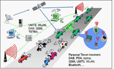
Fig. 2: Different wireless applications used by road participants
EMDs by nature exist all the time but some of them lead to electromagnetic interference (EMI). In the automotive sector where a person’s life is involved, wireless communication has to be extremely robust. This is the reason why 3GPP TR 22.866 V16.2.0 prescribes very strict requirements towards the quality of service.
There are different kinds of EMDs: narrowband and broadband, continuous and intermittent, intentional and unintentional… This blog will focus on narrowband continuous wave disturbances or CW EMDs.
A CW EMD represents a signal with constant amplitude, phase and frequency. The disturbance can be unintentional or intentional. Irrespective of the disturbance’s nature, there is a source from which this disturbance originates. This source can disturb other wireless communication protocols constantly or temporarily. Both ITS G5 and C-V2X are using orthogonal frequency division multiplexing (OFDM) methods to transmit signals. Figure 3 represents a simplified version of the OFDM technique. The communication can be conditionally split into three parts: transmitter part, communication volume, in which CW EMD is present, and receiver part. The signal is represented in the frequency-domain but during the transmission it has to be represented in the time-domain. This is why there are two transformations in transmitter and receiver which are represented by inverse discrete Fourier transform (IDFT) and discrete Fourier transform (DFT) blocks. The transmitted signal sn (n represents the subcarrier index) is disturbed with CW EMD and then the disturbed signal rn ends up at the receiver. The influence of CW EMD in OFDM systems can be dual. It can disturb only one subcarrier or multiple. The former is valid irrespective of CW EMD power but the latter depends on the CW EMD power – the bigger the power value, the more subcarriers are disturbed. This happens due to the phenomenon which is called spectral leakage. It happens when a non-integer number of periods of a signal is sent to the DFT.
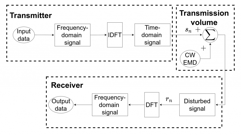
Fig. 3: A simplified version of OFDM technique with the presence of CW EMD
The spectral leakage phenomenon can be seen on Figs. 4 and 5 which represent the amplitude of CW EMD throughout OFDM subcarriers. In both Figs. 4 and 5 CW EMD is related to the OFDM signal with 64 subcarriers using the signal-to-interference ratio (SIR) of 30 dB. Figure 4 represents the case when CW EMD coincides with the signal, so the CW EMD period is an integer in terms of signal periods. It can be seen that CW EMD disturbs only one subcarrier and does not leak to other subcarriers, so there is no spectral leakage. Figure 5 represents exactly the opposite case when the spectral leakage is maximum. CW EMD in Fig. 5 happens exactly when the spectral leakage is right in between two adjacent subcarriers. The case when there is no spectral leakage can be “cured” by implementing, for example, the Hamming coding along with the interleaving. Hence no degradation in performance due to the spectral leakage phenomenon can be noticed. However, this is not the case for the cases when spectral leakage does happen.
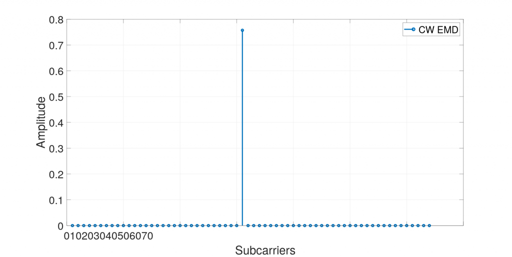
Fig. 4: CW EMD when there is not spectral leakage
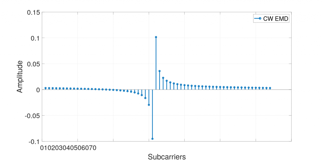
Fig. 5: CW EMD when spectral leakage is maximum
Multiple techniques and methods can be used to tackle the CW EMD problem. They can be subdivided into two groups: cancellation and filtering. Unfortunately, these techniques are based on assumptions that only improve the OFDM performance with the presence of CW EMD under specific conditions. The conditions imply limitations that are better to avoid in AVs. For this, one may need to update and amend current standards. Some researchers have already pointed on these standardization gaps and proposed their vision on possible solutions. The early-stage researcher five (ESR5) of the SAS project is currently working on such solutions finalizing one of them. The essence of his work is to guarantee by design that communication in future autonomous systems will be as robust as possible in a harsh electromagnetic environment.
About the Author: Aleksandr Ovechkin
 Aleksandr graduated from NRU “MPEI” (Russia) with a Master’s degree which was dedicated to investigating the work of battery chargers during short circuits on the DC distribution systems. Later he joined the structural design engineering team and worked there in the electrical engineering department. While working in a company, Aleksandr didn’t quit research activity and he decided, after getting useful work experience, to completely focus on his research as a PhD student.
![]()